Study Notes
Overview
Potential difference — commonly called voltage — sits at the heart of the OCR GCSE Physics electricity unit (Specification Reference 3.2). It is the quantity that drives charge around a circuit, and understanding it is essential for tackling calculation questions, circuit diagram tasks, and extended-response questions that can be worth up to six marks. OCR assesses this topic across both Foundation and Higher tiers, with Higher candidates additionally expected to distinguish potential difference from electromotive force (e.m.f.) and to handle more complex multi-component circuits.
The topic connects directly to Ohm's Law (V = IR), energy in circuits (E = QV), and the behaviour of series and parallel circuits. Exam questions typically ask candidates to define potential difference, calculate values using given formulae, draw or interpret circuit diagrams with correctly placed meters, and explain how voltage is distributed across components. A solid grasp of this topic therefore unlocks marks across multiple question types.
Key Concepts
Concept 1: The Definition of Potential Difference
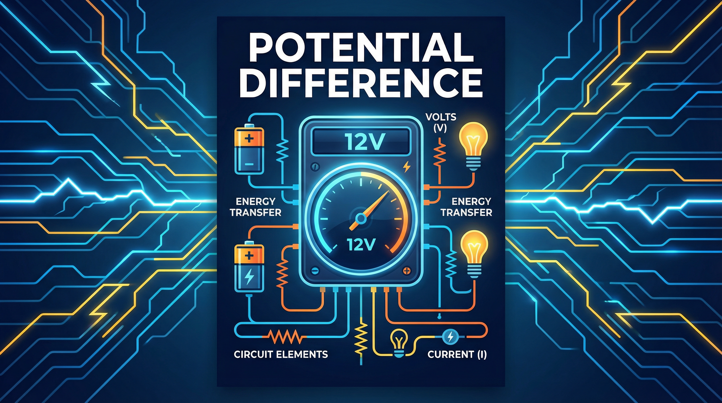
Potential difference (p.d.) is defined as the energy transferred per unit charge as charge moves between two points in a circuit. The formal equation is:
V = E ÷ QWhere V is potential difference in volts (V), E is energy transferred in joules (J), and Q is charge in coulombs (C). This means that a potential difference of 1 volt exists between two points when 1 joule of energy is transferred for every 1 coulomb of charge that passes.
Analogy — The Water Park Pump: Think of a battery as a water pump at a theme park. The pump lifts water to the top of a slide, giving it gravitational potential energy. The height of the slide represents the potential difference — the greater the height, the more energy each unit of water has. As the water slides down and passes through the ride, it releases that energy. Charge in a circuit behaves identically: the battery gives energy to each coulomb of charge, and that energy is released as the charge passes through components such as resistors, bulbs, and motors.
Why this matters for the exam: The command word 'State' or 'Define' applied to potential difference is worth 1 mark. The examiner's mark scheme awards this mark specifically for the phrase 'energy transferred per unit charge' or 'work done per unit charge'. Any other phrasing risks losing the mark.
Concept 2: Measuring Potential Difference — The Voltmeter
Potential difference is measured using a voltmeter, connected in parallel across the component being measured. This is one of the most frequently tested practical points in the entire electricity unit.
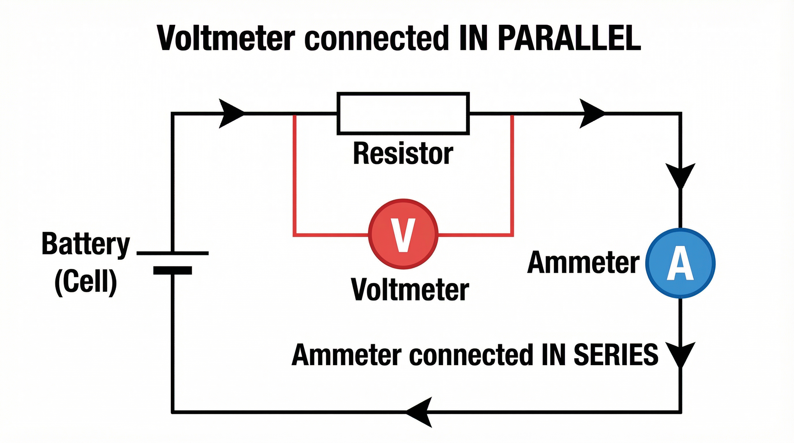
A voltmeter must be connected in parallel because it has an extremely high internal resistance — ideally approaching infinity. This means negligible current flows through the voltmeter itself, so it does not disturb the circuit it is measuring. If a voltmeter were incorrectly placed in series, its high resistance would block the current and the circuit would effectively stop working.
Contrast this with an ammeter, which measures current and must be connected in series. An ammeter has a very low resistance so that it does not impede the current it is measuring.
Examiner's mark scheme note: Questions that ask candidates to 'draw a circuit diagram to measure the potential difference across a resistor' will award 1 mark specifically for the voltmeter drawn in parallel across that component, with the correct symbol (a circle containing the letter V).
Concept 3: Ohm's Law — V = IR
The most widely used formula in this topic is Ohm's Law:
V = I × RWhere V is potential difference in volts (V), I is current in amperes (A), and R is resistance in ohms (Ω). This formula can be rearranged to find any of the three quantities:
| Formula | Use when... |
|---|---|
| V = I × R | You know current and resistance, want potential difference |
| I = V ÷ R | You know potential difference and resistance, want current |
| R = V ÷ I | You know potential difference and current, want resistance |
This formula is given on the OCR formula sheet, but candidates must still memorise the rearrangements and know how to apply them correctly. The examiner awards 1 mark for correct substitution of values prior to the final calculation — so always write the formula and substitution step explicitly.
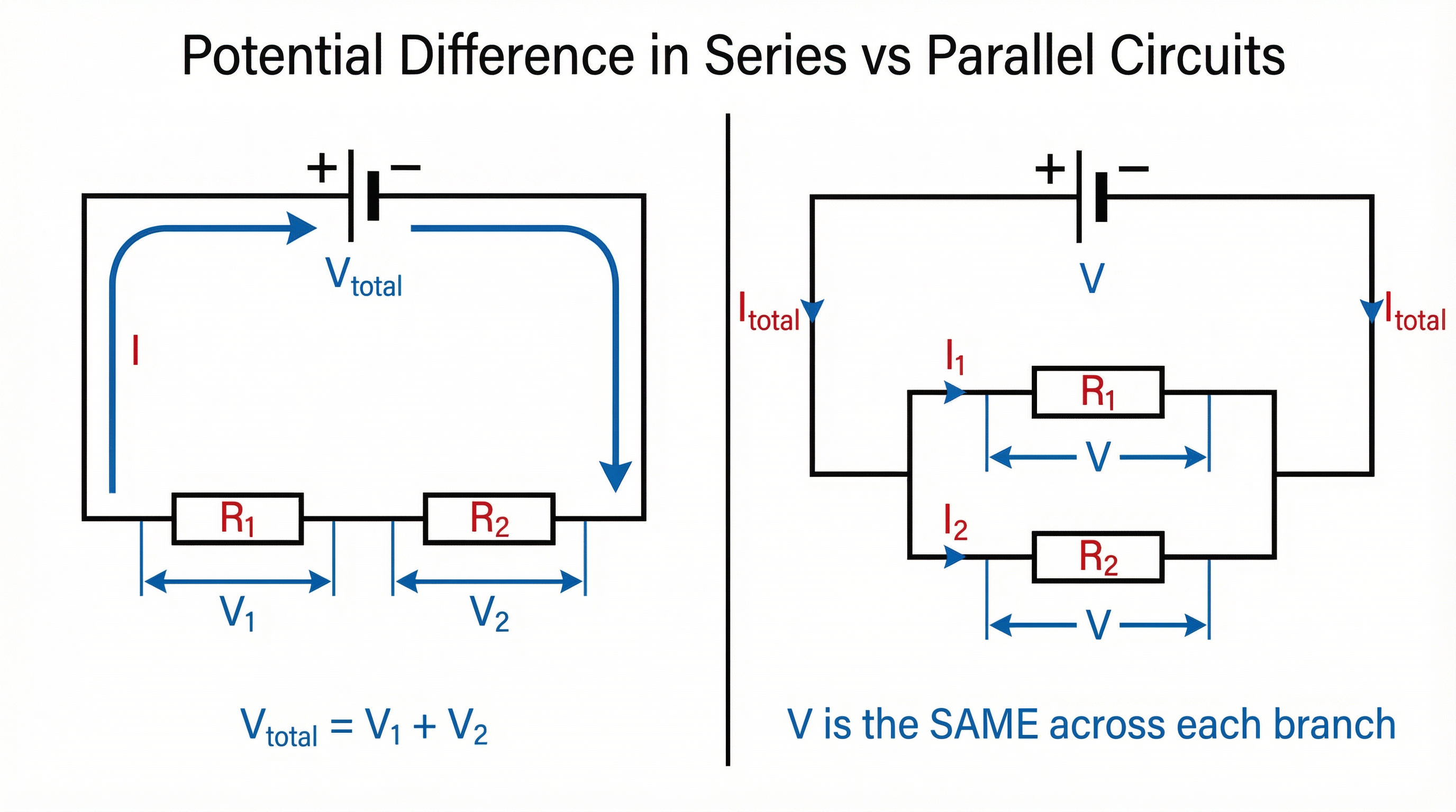
Concept 4: Potential Difference in Series Circuits
In a series circuit, all components are connected in a single, unbroken loop. There is only one path for current to flow. The key rules are:
- The current is the same at every point in the circuit.
- The total potential difference of the supply is shared between the components: V_total = V₁ + V₂ + V₃ + ...
This sharing occurs because each component has resistance, and as charge passes through each one, it transfers some of its energy. A component with greater resistance will have a larger share of the total potential difference across it.
Example: A 12 V battery is connected to two resistors in series. The potential difference across R₁ is 7 V. What is the potential difference across R₂?
V_total = V₁ + V₂ → 12 = 7 + V₂ → V₂ = 5 V
Concept 5: Potential Difference in Parallel Circuits
In a parallel circuit, components are connected in separate branches, each providing an independent path for current. The key rules are:
- The potential difference across each branch is the same, equal to the supply voltage.
- The total current is the sum of the currents in each branch: I_total = I₁ + I₂ + I₃ + ...
This is because each branch connects directly between the same two points in the circuit — the positive and negative terminals of the supply — so each branch 'sees' the full supply voltage.
Memory hook: 'Series Splits the V; Parallel Preserves the V'
Concept 6: Potential Difference vs. Electromotive Force (e.m.f.) — Higher Tier
This distinction is assessed at Higher tier and is a common source of confusion. Electromotive force (e.m.f.) is the total energy given to each coulomb of charge by the source (battery or power supply). Potential difference is the energy transferred from each coulomb as it passes through a component.
In an ideal circuit (no internal resistance), e.m.f. equals the total p.d. across all external components. In a real circuit, some energy is dissipated inside the battery due to its internal resistance, so the terminal voltage (the actual p.d. available to the external circuit) is slightly less than the e.m.f.
Mathematical Relationships
| Formula | Symbols | Status |
|---|---|---|
| V = E ÷ Q | V = potential difference (V), E = energy (J), Q = charge (C) | Given on formula sheet |
| V = I × R | V = potential difference (V), I = current (A), R = resistance (Ω) | Given on formula sheet |
| V_total = V₁ + V₂ (series) | Sum of component voltages equals supply voltage | Must understand |
| V same across branches (parallel) | Each branch voltage equals supply voltage | Must understand |
Unit Conversions — candidates frequently lose marks here:
| Given unit | Conversion to Volts |
|---|---|
| 1 millivolt (mV) | = 0.001 V = 1 × 10⁻³ V |
| 1 kilovolt (kV) | = 1000 V = 1 × 10³ V |
| 250 mV | = 0.25 V |
| 50 mV | = 0.05 V |
| 3.3 kV | = 3300 V |
Always convert to standard units (V) before substituting into any formula.
Practical Applications
The measurement of potential difference is a core practical skill in OCR GCSE Physics. In the required practical for investigating resistance, candidates connect a voltmeter in parallel across a resistor and an ammeter in series, varying the potential difference and recording current to plot a V–I graph. The gradient of this graph gives the resistance (R = V/I).
Real-world applications of potential difference include: the 230 V mains supply in UK homes, the 12 V battery in a car, the 1.5 V cell in a torch, and the very small millivolt signals produced by sensors in medical equipment. Understanding how potential difference drives energy transfer is fundamental to electrical engineering, electronics, and renewable energy systems.