Study Notes
Overview
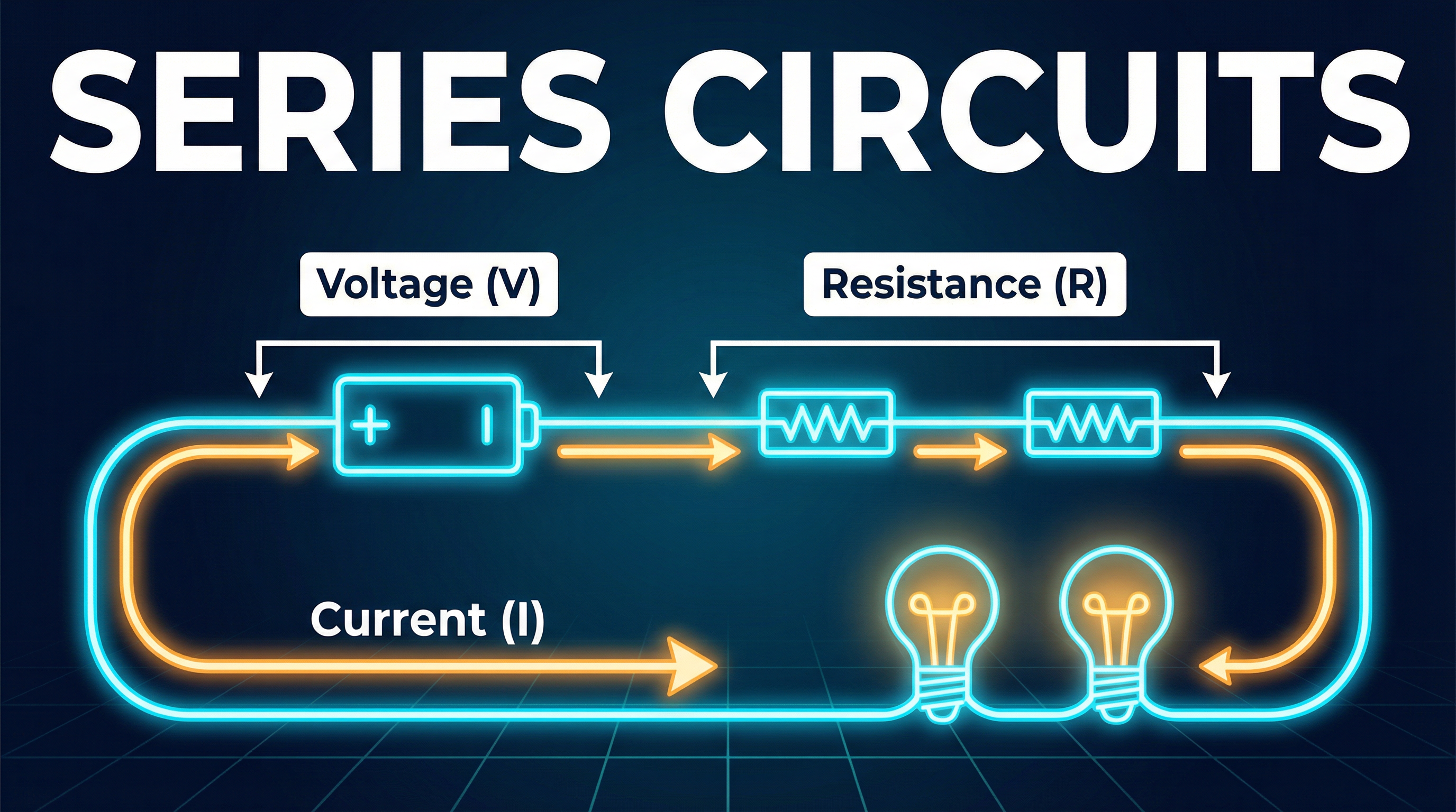
Welcome to your deep dive into Series Circuits for OCR GCSE Physics. This topic is a cornerstone of the electricity module, and a solid understanding here will pay dividends across the entire specification. In a series circuit, components are connected end-to-end, forming a single, unbroken loop. This simple arrangement dictates two fundamental rules that you must know: current is the same everywhere, and the total voltage is shared between the components. Examiners rigorously test these concepts, often combining them with Ohm's Law (V=IR) and resistance calculations. Expect to see questions ranging from simple definitions and calculations to more complex problems where you must analyse the effect of changing a component. This guide will equip you with the knowledge, exam technique, and memory tools to tackle them all with confidence.
Key Concepts
Concept 1: Conservation of Current
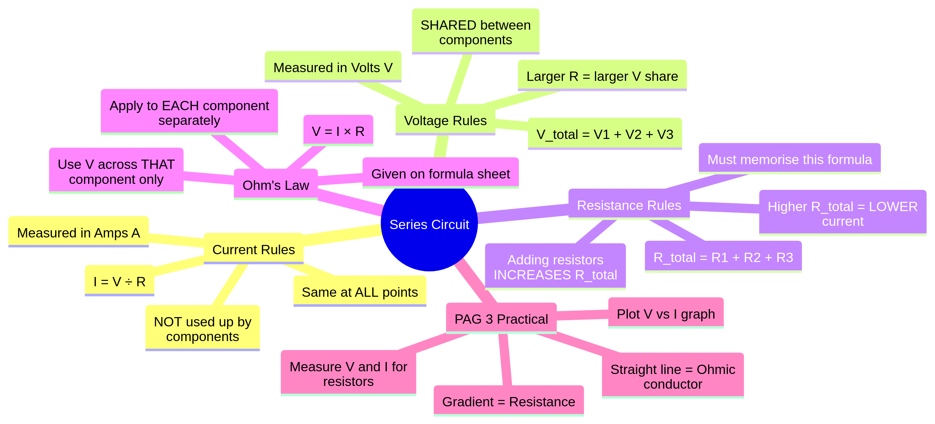
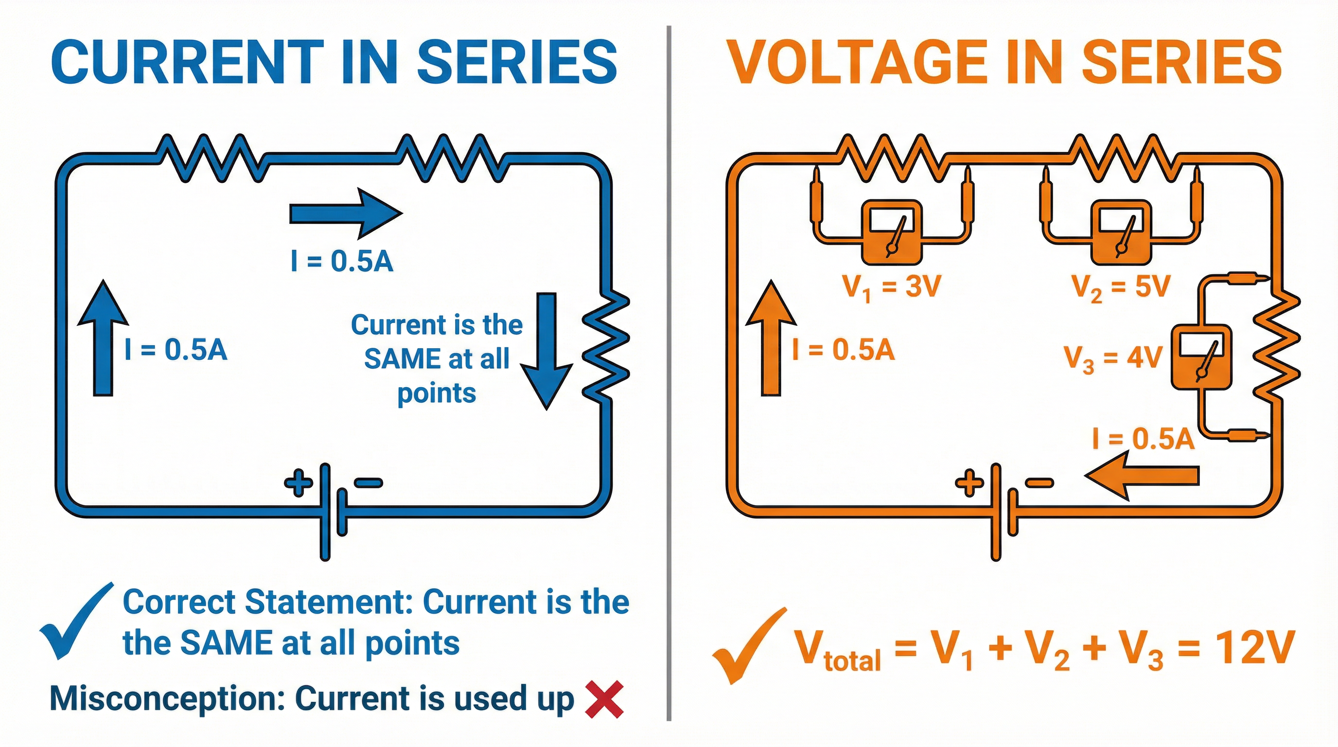
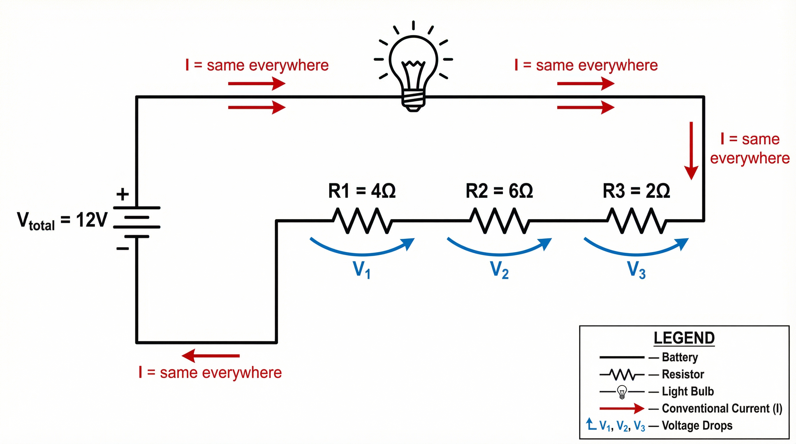
In a series circuit, there is only one path for the electric current to flow. This means that the rate of flow of charge (the current) must be the same at any point in the circuit. It is not 'used up' or diminished as it passes through components. An ammeter placed anywhere in a series circuit will give the same reading. This is a direct consequence of the conservation of charge.
Examiner's Note: A common and costly mistake is to state that current is lower after a resistor. This is incorrect. Credit is awarded for stating that current is constant at all points in a series loop.
Concept 2: Sharing of Potential Difference (Voltage)
Potential difference (voltage) is the energy transferred per unit of charge. The total voltage provided by the power supply (e.g., a battery) is shared between all the components in the series circuit. The sum of the potential differences across each individual component is equal to the total potential difference of the supply.
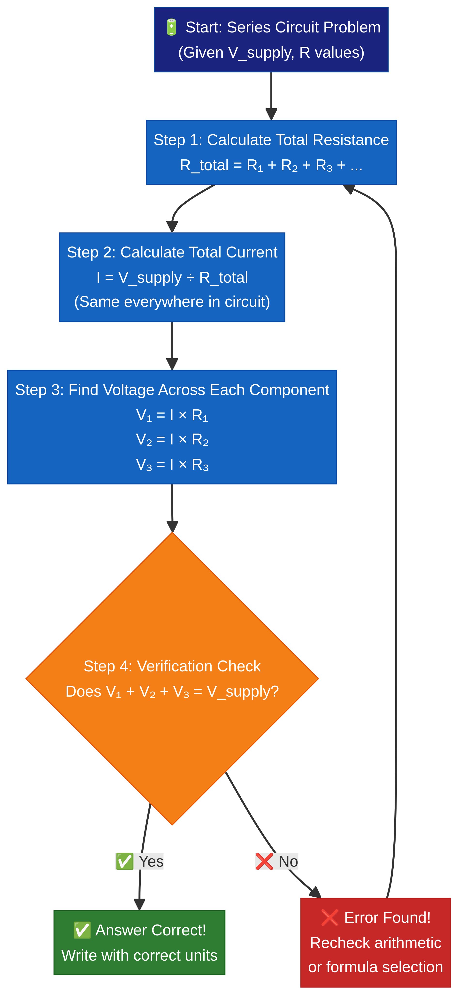
Formula: V_supply = V₁ + V₂ + V₃ + ...
This means that components with higher resistance will take a larger share of the voltage, while components with lower resistance will take a smaller share. This relationship is governed by Ohm's Law.
Concept 3: Total Resistance
Adding resistors in a series circuit increases the overall total resistance. The total resistance is simply the sum of the individual resistances of each component in the loop. This is a rule you must memorise, as it is not provided on the formula sheet.
Formula (Must Memorise): R_total = R₁ + R₂ + R₃ + ...
Example: If three resistors of 2Ω, 4Ω, and 6Ω are connected in series, the total resistance is 2 + 4 + 6 = 12Ω. Adding another resistor would further increase this total, and consequently, decrease the total current flowing in the circuit (assuming the supply voltage remains constant).
Mathematical/Scientific Relationships
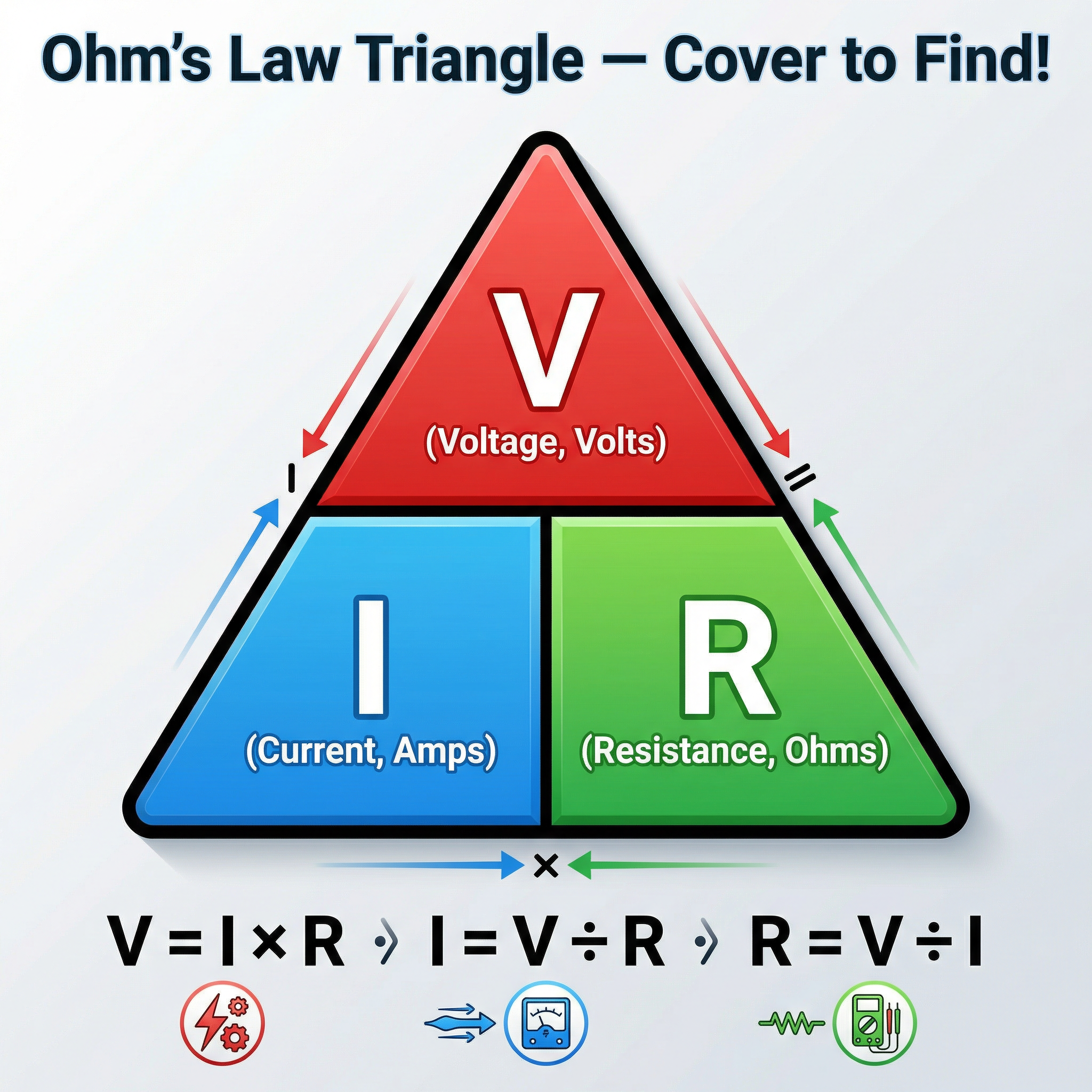
Ohm's Law (Given on formula sheet)
Ohm's Law is the central equation linking voltage, current, and resistance. You must be fluent in its application and rearrangement.
V = I × R(Voltage = Current × Resistance)I = V / R(Current = Voltage / Resistance)R = V / I(Resistance = Voltage / Current)
Crucial Application: When applying Ohm's Law to a single component in a series circuit, you MUST use the voltage across that specific component, not the total supply voltage. To find the voltage across a single resistor, you first need to calculate the total current flowing through the circuit.
Practical Applications
Series circuits have several real-world uses, although they are less common in household wiring than parallel circuits. A classic example is a string of simple, old-fashioned fairy lights. If one bulb breaks, the entire circuit is broken, and all the lights go out. This is a key disadvantage. They are also used in simple switches and some sensor circuits where a change in resistance of one component (like a thermistor or LDR) affects the voltage across another, which can be used to trigger an action.
Required Practical (PAG 3): Investigating Resistance
Examiners frequently test your knowledge of the practical used to investigate the factors affecting resistance. For a series circuit, this often involves building a circuit to determine the resistance of a component.
- Apparatus: Power supply, ammeter, voltmeter, component (e.g., a resistor), and connecting leads.
- Method: Construct a series circuit containing the power supply, ammeter, and the component. Connect the voltmeter in parallel across the component. Record the readings on the ammeter (current) and voltmeter (voltage). Vary the voltage of the supply and take several pairs of readings. Plot a graph of Voltage (y-axis) against Current (x-axis). The gradient of this graph (ΔV/ΔI) gives the resistance of the component.
- Common Errors: Connecting the voltmeter in series or the ammeter in parallel. Misreading the scales on the meters. Not taking a range of readings to plot a reliable graph.
Podcast Episode
For an in-depth audio walkthrough of this topic, including exam tips and a quick-fire quiz, listen to our dedicated podcast episode.